CM MACCHINE
PLANER ON 1, 2 OR 4 SIDES
-KSL FS 2200 MODEL -
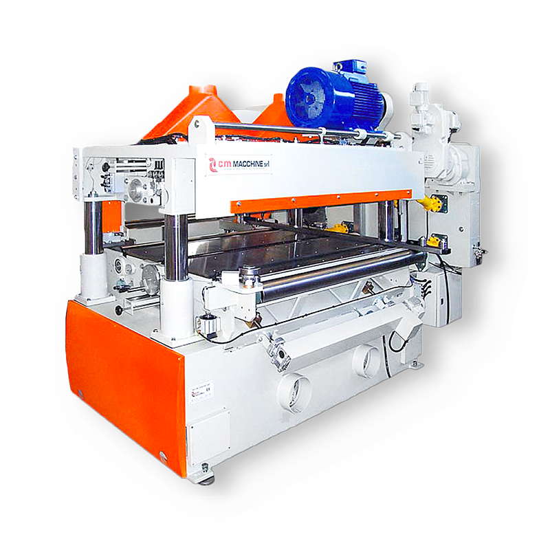
The KSL FS 2200 model wood planer belongs to the highest range in the wide range of CM Macchine machinery and is the result of more than 25 years of experience in the sector and hundreds of machines sold all over the world.
KSL FS 2200 is a machine characterized by very high power and structural solidity and was designed by CM Macchine to plan wood at high speed
Created for working planks, matchboards, floors and other large elements for prefabricated houses or for planing curved elements for large structures, it is equipped with a cardan transmission and 4 or 6 lifting columns.
The KSL FS 2200 wood planer can be made 1, 2 or 4 sides and can be equipped with a turntable for use with curved elements.
With maximum working dimensions of 300 mm in height and 2200 mm in width, it is also widely customizable in configuration according to customer needs.
It can be equipped with a multi-blade shaft and additional, even universal, shafts.
KSL FS - ENG
Send download link to:
KSL FS
MODEL COMPOSITION
MACHINE STRUCTURE
Made of heavy electro-welded mechanical carpentry characterized by high resistance and stability.
Characterized by a modular shape, with a fixed height worktop and a mobile upper part.
MOBILE WORK SURFACE
Removal surface with surface planer sliding on dovetail guides.
FIXED WORKTABLE
Equipped with 4 chromed columns with 4 high precision reducers and movable upper part.
HORIZONTAL KNIFE HOLDER CYLINDERS
Horizontally positioned knife holder cylinders.
ROLLERS
Towed by cardan shaft.
OPTIONAL ITEMS
-Opposed vertical shafts
-Motorized extractor
THE PHASES IN DETAIL
WORKING PROCESS
The working process of the KSA wood planer consists of three stages:
1. The workpiece is inserted into the planer and pulled in by the feeding rollers.
2. The piece is worked by the surfacing planer and then by the thickness planer, finally by the spindle moulder units and, if present, by the chamferings.
3. The workpiece thus worked comes out of the machine sliding on an exit roller conveyor.
Technical data | ||
Minimum working width | mm | 50 |
Minimum working width with chamferings | mm | 80 |
Maximum working width | mm | 2200 |
Minimum working height | mm | 20 |
Minimum working height (on request) | mm | 15 |
Maximum working height | mm | 300 |
Electronically variable feed speed | m/min | da 25 a 120 |
Maximum removal | mm | 10 |
Maximum removal with enhanced motors | mm | 15 |
CM MACCHINE


